Several approaches could be used to determine the maximum load . For this example, the following procedure will be used:
3. Using the area and the allowable normal stress, the corresponding normal force acting on surface can be computed.
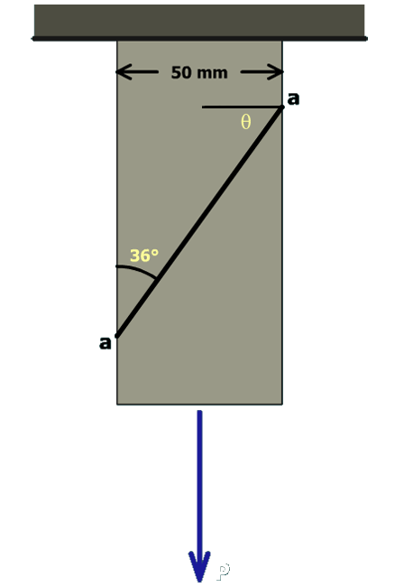
4. Using the angle , the maximum load corresponding to this normal force can be computed.