Home
Chapter 5: Axial Deformation
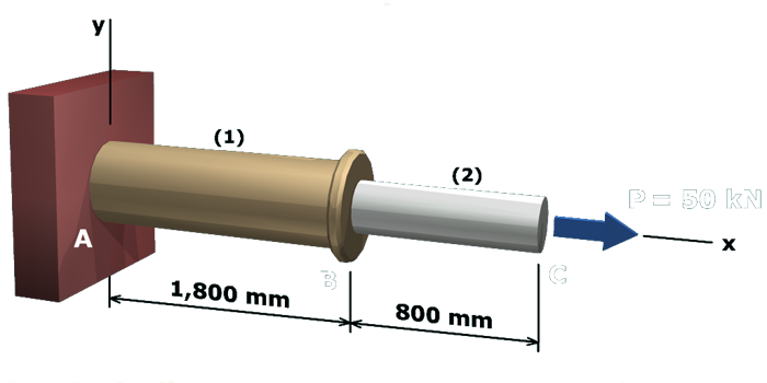
M5.3: Deformation of a Compound Axial Member
Deformation in Segment (1)
State the Problem
Plan the Solution
Table of Contents
Deformation in Segment (1)
Allowable Deformation in Segment (2)
Minimum Cross-Sectional Area for Segment (2)
Minimum Diameter for Segment (2)
scene
4
of
7
Cut a free-body diagram
(
FBD
)
through segment
(
1
)
.