Note: Assume a positive internal force (i.e., tension).
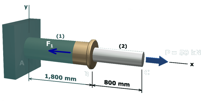
The figure shows the free body diagram of the compound axial member with respect to the joints B and C. The free body diagram cuts through member 1. The x axis is taken along the common axis of the members. The y axis is taken perpendicular to the x axis. The load at C is P which equals 50 kilo newtons in the positive x direction and the axial force in member 1 is F subscript 1 in the negative x direction.

The deformation of segment (1) can be computed from:

δ1=F1L1A1E1=(50 kN)(1,800 mm)(1,000 N/kN)(314.16 mm2)(100,000 N/mm2)=2.86 mm

where the cross-sectional area of segment (1) is:

A1=π4 (20 mm)2=314.16 mm2