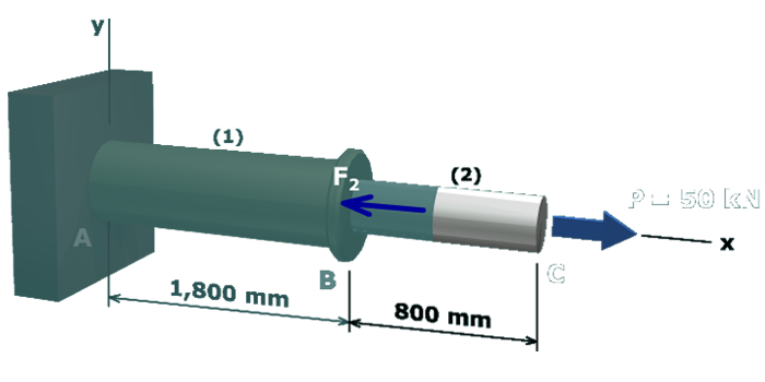
The figure shows the free body diagram of the compound axial member with respect to joint C. The free body diagram cuts through member 2. The x axis is taken along the common axis of the members. The y axis is taken perpendicular to the x axis. The load at C is P which equals 50 kilo newtons in the positive x direction and the axial force in member 2 is F subscript 2 in the negative x direction.

The maximum elongation that is acceptable for segment (2) is δ2=2.14 mm. Rearrange the axial force-deformation equation to solve for the minimum acceptable area A2.

δ2=F2L2A2E2

A2=F2L2δ2E2=(50 kN)(800 mm)(1,000 N/kN)(2.14 mm)(70,000 N/mm2)=267.02 mm2