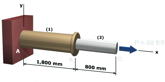
The figure shows a compound axial member consisting of a larger cylindrical segment A B which is marked 1 having a length of 1800 millimeters flanged to another cylindrical segment B C which is marked 2 having a length of 800 millimeters. Segment 1 is fixed to a wall at the point A. The x axis is taken along the common axis of the two cylindrical members and the y axis is taken perpendicular to the x axis along the wall. The tension load at the free end of segment 2 is P which equals 50 kilo newtons oriented in the positive x direction.

If the diameter of segment (2) is less than 18.44 mm, segment (2) will elongate more than 2.14 mm, which will cause C to deflect more than 5 mm relative to support A.


Finished