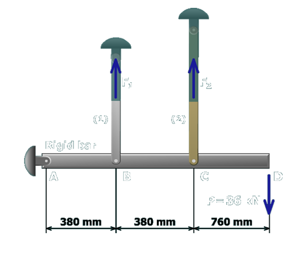
The figure shows the free body diagram of the rigid bar A B C D pinned at A and supported by vertical rods labeled 1 and 2 at B and C. The separation between A and B is 380 millimeters. The separation between B and C is 380 millimeters and the separation between C and D is 760 millimeters. The load at D is P which equals 36 kilo newtons directed vertically downwards. The free body diagram cuts through the vertical members 1 and 2. The reaction forces on the members 1 and 2 are F subscript 1 and F subscript 2 directed vertically upwards.

MA=F1(380 mm)+F2(760 mm)-P(1,520 mm)=0

A second equation involving the internal forces F1 and F2 must be developed to solve this problem. To do this, the geometry of the structure and its corresponding deformations will be considered.