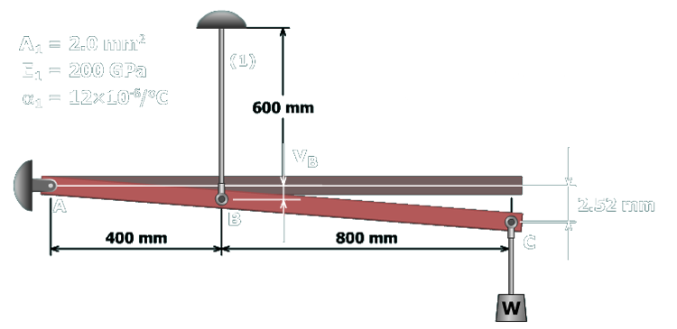
The figure shows a rigid bar A B C pinned at A and supported at B by a wire labeled 1 of length 600 millimeters. The separation between A and B is 400 millimeters and the separation between B and C is 800 millimeters. A weight W is shown attached to the bar at C. The parameters listed on the top left are A subscript 1 which equals 2 square millimeters, E subscript 1 which equals 200 giga pascals and alpha subscript 1 which equals 12 times 10 to the negative 6 per degree Celsius. The right end of the rod marked C is deflected downward by 2.52 millimeters and the elongation of the wire at point B is v subscript B.

To determine the normal strain in wire (1), the deformation in the wire must be determined. Since the wire is attached to the rigid bar, the deformation of the wire will equal the rigid bar deflection at point B.

The rigid bar remains perfectly straight when it deflects. Therefore, the deflection at B can be determined, using the principle of similar triangles, from the measured rigid bar deflection at C.

vB400 mm=2.52 mm1,200 mm  vB=0.84 mm