Temperature change
ΔT = +65°C
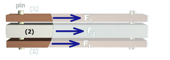
Copper bars (1)
A1 = 360 mm2
E1 = 120 GPa
α1 = 16.0 × 10⁻⁶/°C
Aluminum bar (2)
A2 = 720 mm2
E2 = 70 GPa
α2 = 23.0 × 10⁻⁶/°C
Next, the normal strain in the copper bars will be calculated. A common mistake would be to compute the normal strain using Hooke's Law in this manner:
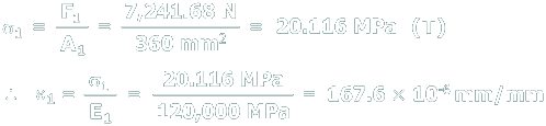
Why is this calculation not correct?