Temperature change
ΔT = +65°C
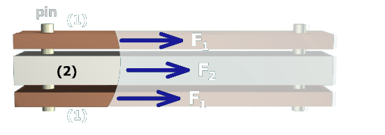
Copper bars (1)
A1 = 360 mm2
E1 = 120 GPa
α1 = 16.0 × 10⁻⁶/°C
Aluminum bar (2)
A2 = 720 mm2
E2 = 70 GPa
α2 = 23.0 × 10⁻⁶/°C
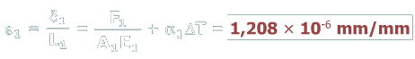
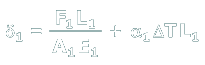
To compute the strain in the copper bars, recall that normal strain is defined as the change in length divided by the initial length. The change in length of the copper bars is deformation δ1:
Dividing this expression by the initial length L1 gives an expression for the normal strain in the copper bars: