Home
Chapter 7: Equilibrium of Beams
M7.3: Step-by-Step Examples
Miscellaneous Beams, Part 1
Introduction
Table of Contents
Simply Supported Beams With Concentrated Loads Only
Simply Supported Beams
Simply Supported Beams With Overhangs
Cantilever Beams
Beams With External Concentrated Moments
Beams With Triangular Loading
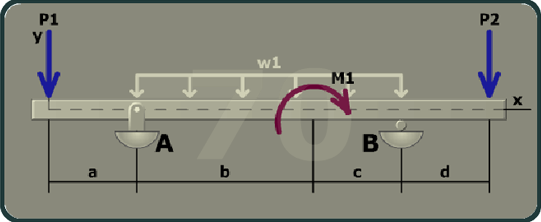
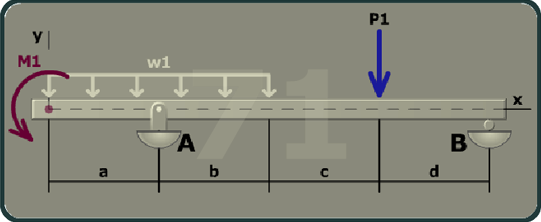
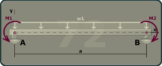
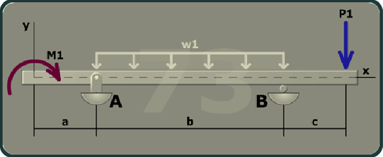
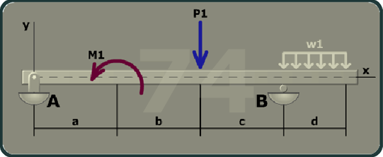
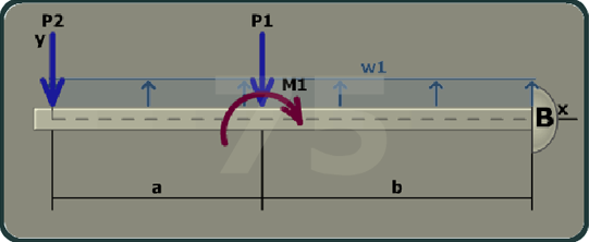
Miscellaneous Beams, Part 1
Miscellaneous Beams, Part 2
scene
9
of
10