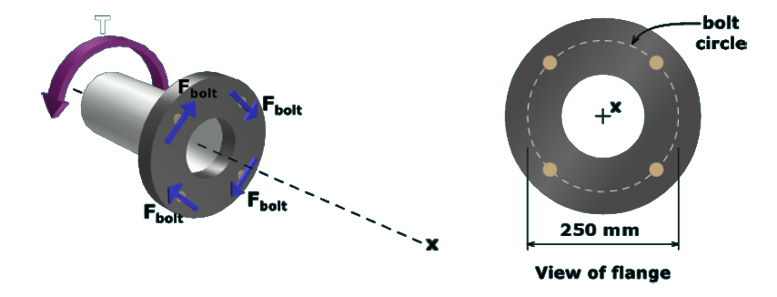
The figure on the left shows a shaft with a flange at one end. The axis of the shaft is along the x axis. The torque at the end of the shaft has a magnitude T and is directed counterclockwise. The force on each of the bolt is F subscript bolt directed opposite to the torque T. The figure on the right shows the front view of the flange. The bolt circle has a diameter of 250 millimeters.  

The diameter of each bolt is 22 mm; therefore, the cross-sectional area of each bolt is:

Abolt=π4 (22 mm)2      =380.133 mm2

The average shear stress in each bolt can now be calculated:

τ=FboltAbolt =(20 kN)(1,000 N/kN)380.133 mm2      =52.6 MPa