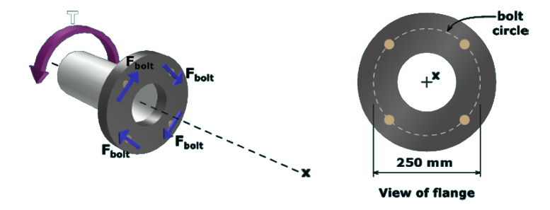
The figure on the left shows a shaft with a flange at one end. The axis of the shaft is along the x axis. The torque at the end of the shaft has a magnitude T and is directed counterclockwise. The force on each of the bolt is F subscript bolt directed opposite to the torque T. The figure on the right shows the front view of the flange. The bolt circle has a diameter of 250 millimeters.  

The bolts are installed on a 250 mm   diameter bolt circle, which means that each bolt is located at a radial distance of 125 mm from the centerline of the flange and shaft.

The torque resisted by each bolt is the product of the bolt force and the  125 mm -  radial distance. The external torque T applied to the shaft and the internal resistance from the bolts must satisfy equilibrium.