The figure on the left shows a shaft with a flange at one end. The axis of the shaft is along the x axis. The torque at the end of the shaft has a magnitude T and is directed counterclockwise. The force on each of the bolt is F subscript bolt directed opposite to the torque T. The figure on the right shows the front view of the flange. The bolt circle has a diameter of 250 millimeters.  

The cross-sectional area of all four bolts would be exposed. It is these surfaces upon which shear stress acts.

The resistance provided by each bolt is given by:

Fbolt=τ Abolt

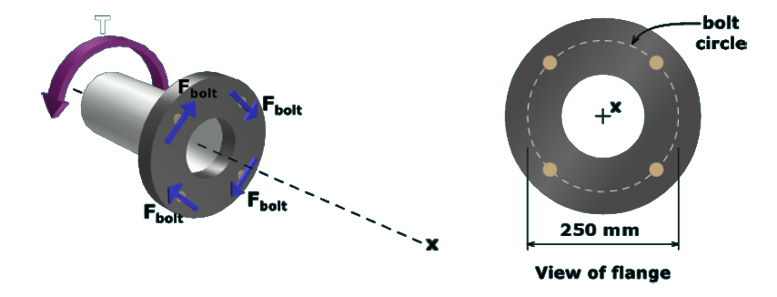
The external torque applied to the shaft must be transmitted through the flanged connection by means of the shear resistance in the bolts.