Home
Chapter 5: Axial Deformation
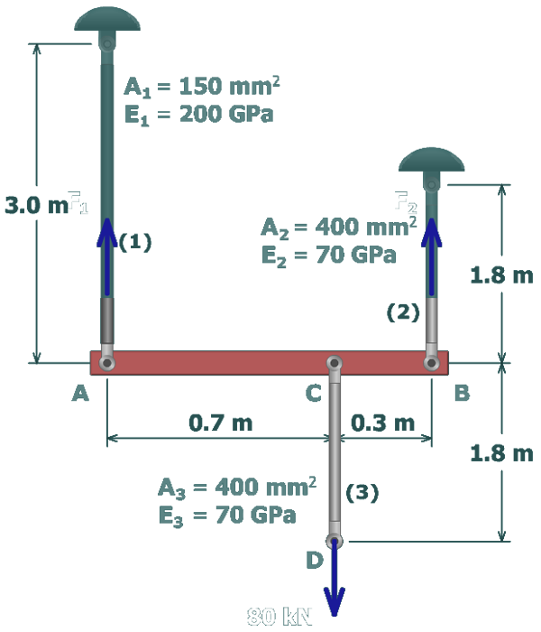
M5.4: Deformations in a Three-rod Assembly
Equilibrium
State the Problem
Table of Contents
Equilibrium
Rod Deformations
Rigid Bar Deflections at A and B
Rigid Bar Deflection at C
Assembly Deflection at D
scene
3
of
7
Begin by drawing a free-body diagram
(
FBD
)
that cuts through rods
(
1
)
and
(
2
)
.