The figure shows the free body diagram of the rigid bar A C B and the supporting rods. The free body diagram cuts through rods 1 and 2. The force along rods 1 and 2 are F subscript 1 which equals 24 kilo newtons and F subscript 2 which equals 56 kilo newtons both of which are directed vertically upwards. The force at the end point D of the support rod C D is F subscript 3 which equals 80 kilo newtons and is directed vertically downwards.

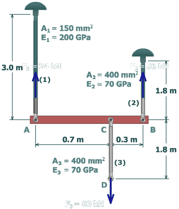
The relationship between the internal force in an axial member and its deformation is given by:

δ=FLAE

Similarly, the deformation of aluminum rod (2) can be calculated as:

δ2=F2L2A2E2   =(56,000 N)(1,800 mm)(400 mm2)(70,000 N/mm2)   =3.60 mm