The figure shows an L shaped rigid bar A B C D with a horizontal segment A B C  of length 750 millimeters and a vertical segment C D of height 300 millimeters. The bar is pinned at C and supported by vertical and horizontal rods labeled 1 and 2 of length 600 millimeters and 150 millimeters at A and D respectively. The other end of the support rods is pinned. A load P which equals 80 kilo newtons directed vertically downwards acts at the point B which is 400 millimeters to the right of C. The bar is deflected downwards at the point A and deflected leftwards at the point D.

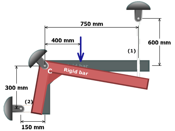
Because each rod is connected to rigid bar ABCD, the deformations in rods (1) and (2) are not independent.

The geometry of the deflected structure will be used to establish the relationship between the elongation in rod (1) and the contraction in rod (2).

The geometric relationship will provide information that is needed to solve the problem.