The figure shows an L shaped rigid bar A B C D with a horizontal segment A B C of length 750 millimeters and a vertical segment C D of height 300 millimeters. The bar is pinned at C and supported by vertical and horizontal rods labeled 1 and 2 of length 600 millimeters and 150 millimeters at A and D respectively. The other end of the support rods is pinned. A load P which equals 80 kilo newtons directed vertically downwards acts at the point B which is 400 millimeters to the right of C. The bar is deflected downwards at the point A and deflected leftwards at the point D. The initial length of the support rod 1 is L subscript 1 and the final elongated length is L subscript final. The downward deflection at A is v subscript A. The initial length of support rod 2 is L subscript 2 and the final compressed length is L subscript final. The leftward deflection is v subscript D.

The deformation in rod (1) can be determined by considering the initial and final lengths of the axial member.

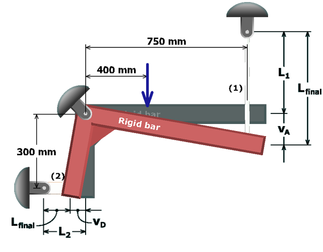
Based on this sketch of the assumed deflected position of the rigid bar, the initial length of rod (1) is:

Linit=L1

and the length after deformation is:

Lfinal=L1+vA

Therefore, the elongation of rod (1) can be written as:

δ1=Lfinal-Linit   =(L1+vA)-L1   =vA