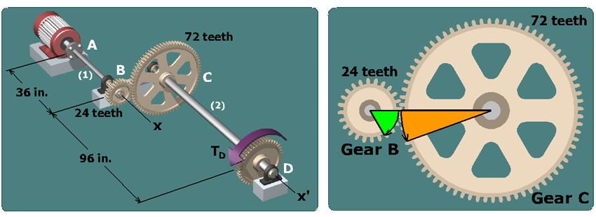
Diagram on the left shows two shafts marked 1 and 2 of length 36 inches and 96 inches respectively. They are connected by two gears at B which has 24 teeth on the shaft 1 and at C which has 72 teeth on the shaft 2. The shaft 1 is connected to a motor at A. The shaft 2 has a gear at D on which a torque T subscript D is applied. Diagram on the right shows two gears marked B and C with 24 teeth and 72 teeth respectively. The sector shows the meshing between the two teeth of the gears B and C.

Consider the detail view of gears B and C shown on the right. The negative rotation angle found for gear B means that gear B will rotate clockwise in this detail view.