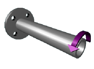
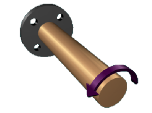
M6.1: Torsion Concepts
Concept Checkpoint
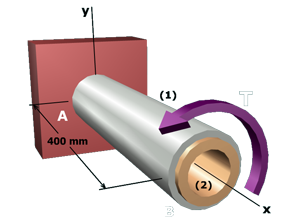
Basic torsion problems involving internal torques, shear stress, and angles of twist.
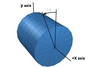
M6.2: Torsion Theory for Circular Sections
Theory
Derive elastic torsion formula and angle of twist formula.
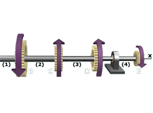
M6.3: Sign Conventions for Torsion Analysis
Theory
Sign conventions used for internal torque, shaft element twist angles, and rotation angles.
M6.4: Allowable Torque in a Pipe Shaft
Example
Given an allowable shear stress, determine the maximum torque that can be applied to a pipe shaft.
M6.5: Minimum Diameter for a Solid Shaft
Example
Determine the minimum diameter required for a solid shaft.
M6.6: Twisting of a Compound Torsion Member
Example
Determine minimum shaft diameter required to satisfy a twist angle limit.
M6.7: Multiple Torques
Example
Use both the elastic torsion formula and the angle of twist formula to determine shear stresses and rotation angles.
M6.8: Maximum Torque Based on Twist Angle
Example
Based on a twist angle limit, determine the maximum torque that can be applied to a gear.

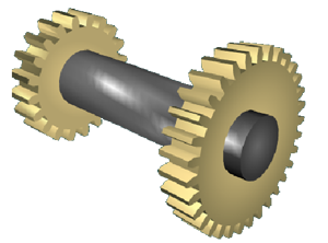
M6.9: Gear Basics
Theory | Concept checkpoints
Basic gear relationships for torque, rotation angle, rotation speed, and power transmission.
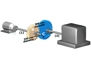
M6.10: Gear Trains: Torque and Shear Stress (Two Shafts)
Concept checkpoints
Basic calculations involving two shafts connected by gears.
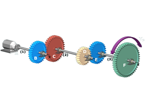
M6.11: Gear Trains: Torque and Shear Stress (Three Shafts)
Concept checkpoints
Basic calculations involving three shafts connected by gears.
M6.12: Gear Trains: Angles of Twist
Concept checkpoints
Basic twist and rotation angle calculations involving two shafts connected by gears.
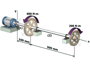
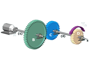
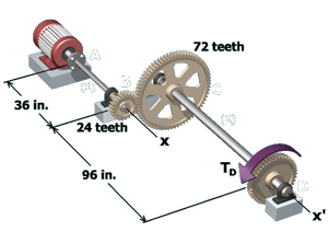
M6.13: Two Shafts Connected by Gears
Example
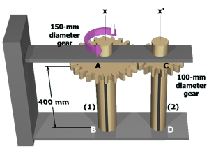
Determine the shear stress in each shaft and the rotation angle at the free end.
M6.14: Gear Trains: Power Transmission (Two Shafts)
Concept checkpoints
Basic calculations involving power transmission in two shafts connected by gears.
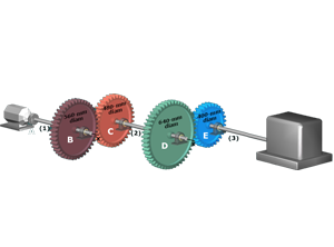
M6.15: Gear Trains: Power Transmission (Three Shafts)
Concept checkpoints
Basic calculations involving power transmission in three shafts connected by gears.
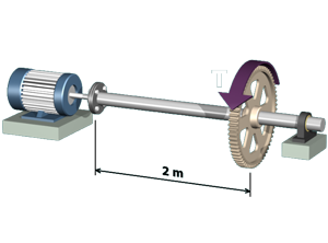
M6.16: Determine Power Transmitted by a Shaft
Example
Determine the maximum power that can be transmitted by a shaft within limits on shear stress and twist angle.
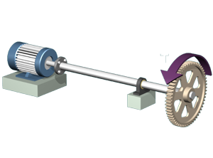
M6.17: Shaft Diameter Based on Power
Example
Determine the minimum diameter required to transmit a specified power.
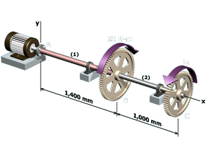
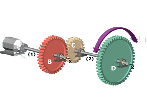
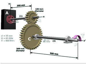
M6.18: Motor-driven Shafts
Example
Determine the maximum shear stress in two gear-connected shafts. Also, determine the rotation angle of a gear.
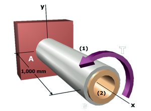
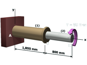
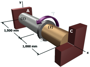
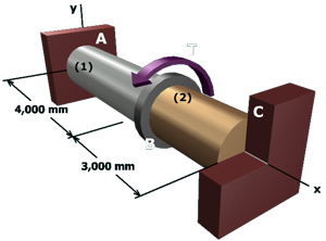
M6.19: Shear Stresses in Coaxial Shafts
Example | Try one
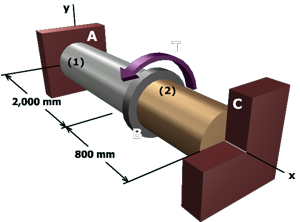
Determine internal torques and shear stresses, and shaft rotation angle in two coaxial shafts.
M6.20: Shear Stresses in End-to-end Shafts
Example | Try one
Determine internal torques, shear stresses, and rotation angles for a compound torsion member.
M6.21: Maximum Torque for Composite Shaft
Example | Try one
Determine the maximum torque that can be applied to a compound torsion member given allowable shear stresses.
M6.22: Maximum Torque Applied to Coaxial Shaft
Example
Given allowable shear stresses for two coaxial shafts, determine the maximum torque that can be applied to the assembly.
M6.23: Shafts With Specified Rotation Angle
Example
Determine the maximum torque that can be applied to a compound torsion member based on a rotation angle limit.
M6.24: Indeterminate Gear Mechanism
Example
Determine the shear stresses produced in two shafts connected by gears.