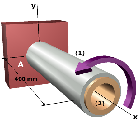
A composite shaft consists of a hollow aluminum shaft bonded to a hollow bronze shaft . The outside diameter of shaft is and the inside diameter is . The outside diameter of shaft is and the inside diameter is .
The allowable shear stresses for the aluminum and bronze materials are and , respectively.
Determine:
• The maximum torque that can be applied to the free end .
• The stresses and developed in the shafts.
• The angle of rotation of end .