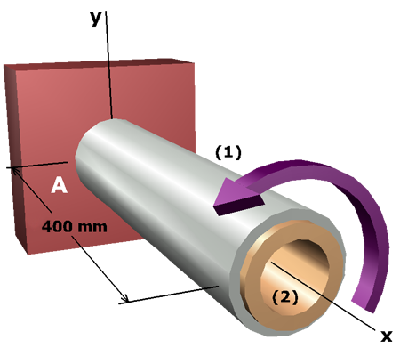
Based on the compatibility equation, there is a stress relationship between the two shafts. It is not likely, therefore, that the shear stress in each shaft will equal its allowable stress limit when the external torque is applied at free end .
One of the shafts will control the design (that is, the shear stress in one shaft will reach its allowable stress while the shear stress in the other shaft will be less that its allowable stress).
We cannot know beforehand whether shaft or shaft will control; therefore, we must take a guess. We will pick one of the shafts and assume that its shear stress is equal to its allowable shear stress.