Diagram shows a shaft A B with an aluminum segment on the outside and a brass shaft in the inside. Both the shafts are centered on the central axis x. A torque T is applied at B. The radial and longitudinal lines are shown on the shaft. The deformation of the shaft is shown with a counterclockwise segment of angle phi subscript B, angle of twist.

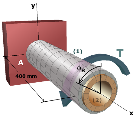
In summary, the internal torques in shafts (1) and (2) are:

T1=1,003.8 N-mT2=1,076.0 N-m

Shear stresses are:

τ1=81.45 MPaτ2=100 MPa

The rotation of end B is:

ϕB=+0.05012 rad   =+2.87 deg

Finished