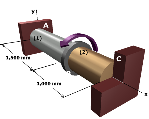
A composite shaft consists of a hollow steel shaft connected to a solid brass shaft at flange . The outside diameter of shaft is and the inside diameter is . The outside diameter of shaft is .
A concentrated torque of is applied to the composite shaft at flange .
Determine
• The torques and developed in the steel and brass shafts.
• The shear stresses and in each shaft.
• The angle of rotation of flange .