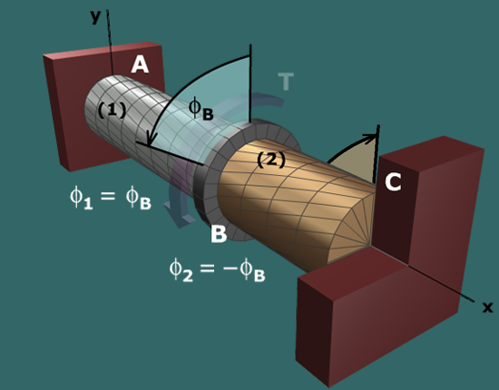
Diagram shows an aluminum shaft A B marked 1 and a brass shaft B C marked 2 with a flange in between at B. Both the shafts are centered on the central axis x. The shaft is supported at A and C. A torque T is applied at B. The radial and longitudinal lines are shown on the shaft. The deformation of the shaft is shown with a counterclockwise segment at B of angle phi subscript B, angle of twist. A caption to the bottom left of the shaft 1 reads: phi subscript 1 = phi subscript B. A caption to the bottom left of the shaft 2 reads: phi subscript 2 = negative phi subscript B.

The rotation angle at B can be found from the geometry of deformation relationship:

ϕ1=ϕB   ϕB=ϕ1

From the torque-twist relationship for shaft (1):

ϕ1=T1L1J1G1=(424.63 N-m)(1,500 mm)(1,000 mm/m)(362,265 mm4)(75,000 N/mm2)               =+0.02344 rad               =+1.34 deg