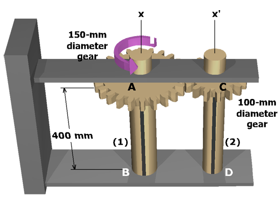
Diagram shows two vertical shafts A B marked 1 and C D marked 2 centered on the x and x prime axes respectively. A gear of 150 millimeter diameter is at A on shaft 1 at a height of 400 millimeters. A gear of 100 millimeter diameter is at C on shaft 2 at a height of 400 millimeters. Above the gear A a torque T is applied on shaft 1 in the counterclockwise direction.

An assembly of two solid brass (G = 44 GPa) shafts connected by gears is subjected to a concentrated torque of 240 N-m as shown.

Shaft (1) has a diameter of 20 mm while the diameter of shaft (2) is 16 mm. Rotation at the lower end of each shaft is prevented.

Determine the shear stress in shaft (2) and the rotation angle at A.