Home
Chapter 6: Torsion
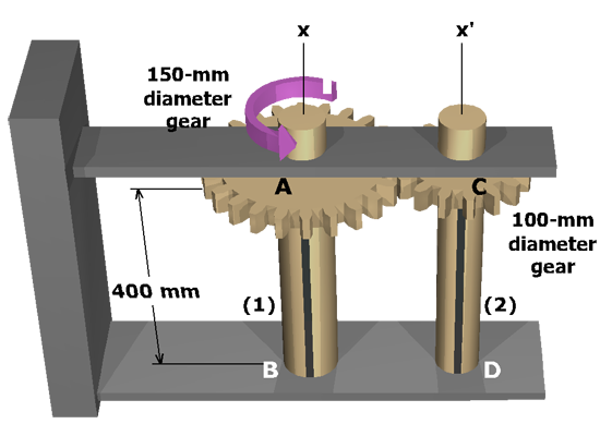
M6.24: Indeterminate Gear Mechanism
Observe the Deformation
State the Problem
Table of Contents
Observe the Deformation
Plan the Solution
Review Sign Conventions
Equilibrium Equations
Geometry of Deformation
Torque-Twist Relationships
Compatibility Equation
Solving for T
2
and T
1
Shear Stresses in Shafts (2)
Rotation Angle of Gear A
Finished
scene
3
of
13
Before beginning the calculations, observe the deformations created in the system by torque
T
.