The first figure shows a beam with pin support at its left end and roller support at its right end. On the pin and roller supports it is marked zero internal moment. A uniform load of 5 kilo newtons per meter acts on the bar between the two supports. A concentrated load of 25 kilo newtons directed vertically downwards acts on the bar slightly to the left of the right end of the bar. The second figure shows a bar with pin support slightly to the right of the left end of the bar and a roller support slightly to the left of the right end of the bar. A uniform load of 8 kilo newtons per meter acts on the bar between the supports. The concentrated loads at the left and right ends of the bar have magnitudes of 25 kilo newtons and 40 kilo newtons respectively and are directed vertically downwards. On the left and right ends of the bar it is marked zero internal moment. The third figure shows a cantilever beam fixed at its left end. A uniform load of 8 kilo newtons per meter acts near the right end of the beam. The right end of the beam is marked zero internal moment. The fourth figure shows a cantilever beam fixed at its right end. A concentrated load of magnitude 40 kilo newtons directed vertically downwards acts on the left end of the beam. Another concentrated load of magnitude 25 kilo newtons acts slightly to the left of the right end of the beam. The left end of the beam is marked zero internal moment.

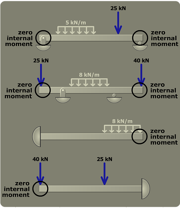
In constructing the bending-moment diagram, it is also helpful to take note of the support condition at each end of the beam. At a free end of the beam, the internal bending moment is always M = 0. Several typical beam end conditions are shown in the figure to the left.