The figure shows a beam of length 10 meters with pin support at its left end and roller support at a distance of 2.5 meters from its right end. The x axis is taken along the length of the beam and the y axis is taken perpendicular to the beam at its left end. A uniform load of 3 kilo newton per meter acts throughout the length of the beam. A concentrated load of 30 kilo newtons directed vertically downwards acts 3 meters from its left end and a concentrated load of 15 kilo newtons directed vertically downwards acts on its right end. The reaction force on the pin support has a magnitude of 23 kilo newtons and is directed vertically upwards. The reaction force on the roller support has a magnitude of 52 kilo newtons directed vertically upwards. The shear force and bending moment diagrams are shown below. The shear force is in units of kilo newtons. The shear force rises from 0 to 23 on the left end, linearly decreases to 14 over a length of 3 meters, drops to negative 16, linearly decreases to negative 29.5 over a length of 4.5 meters, rises to 22.5, linearly decreases to 15 over a length of 2.5 meters and drops to zero at the right end of the beam. The bending moment is in units of kilo newton meter. The bending moment starts from zero on the left end, rises to 55.5 over a length of 3 meters, decreases to negative 46.87 over a length of 4.5 meters and rises to 0 over a length of 2.5 meters.

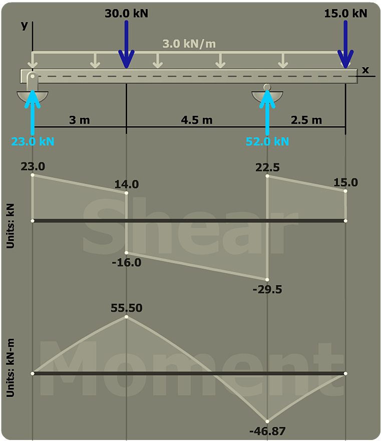
In constructing the bending-moment diagram, start at the left end of the beam (where x = 0) and proceed across the beam to the right. Each bending-moment diagram should start at M = 0 at the left end of the beam and return to M = 0 at the right end. This always occurs in a properly constructed diagram.

If the moment diagram does not return to M = 0 at the right end of the beam, check your equilibrium calculations to make sure that you've correctly determined the beam reactions.