The diagram on the left shows an ā€œIā€ bar consisting of three sections, 1, 2 and 3. The section 1 on top is horizontal with a length of 3.0 inches. The section 2 has a thickness of 0.5 inches and is between the sections 1 and 3. The section 3 is horizontal and has a length of 6.0 inches. The centroid is at the origin of the x y axes on the vertical section 2 at a height of 2.645 inches from the bottom edge of the horizontal section 3 and at a distance 5.355 below the top edge of the section 1. The diagram to the right shows a bent ā€œIā€ bar with the moment M applied in the clockwise direction on the left end and the moment M is applied in the counterclockwise direction on the right end.

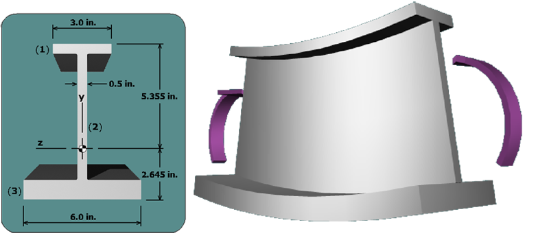
The distance from the neutral axis to the top of the beam is y = +5.355 in. The normal stress at the top of the beam is: