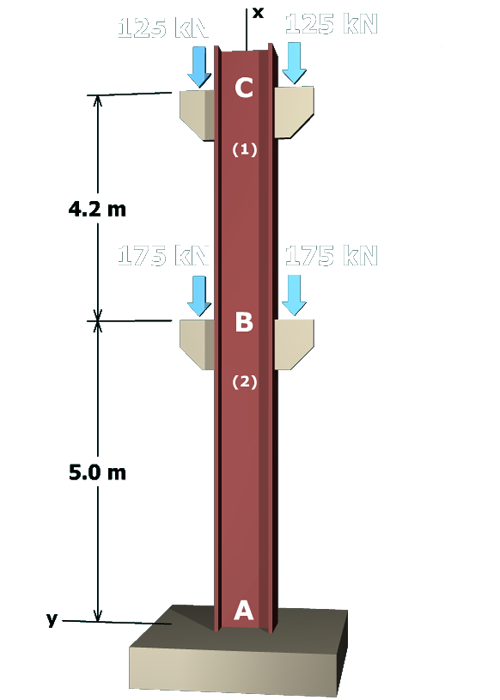
The figure shows a column A B C with its central axis along the x axis. Joint A is at the base. Joint B is 5 meters above joint A and joint C is 4.2 meters above joint C. The forces on either side of joint B have magnitude of 175 kilo newtons and are directed downwards. The forces on either side of joint C have magnitude of 125 kilo newtons and are directed downwards. Points 1 and 2 are marked on the column below joint C and joint B respectively.

To determine the deflection of joint C, the following process will be used:

1. The internal axial force will be determined in both member (1) (i.e., the upper portion of the column between B and C) and member (2) (i.e., the lower portion of the column between A and B).

   This is done by drawing free-body diagrams that expose the internal forces in each member.