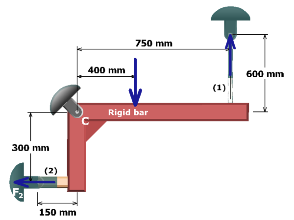
The figure shows the free body diagram of the L shaped rigid bar A B C D with a horizontal segment A B C of length 750 millimeters and a vertical segment C D of height 300 millimeters. The bar is pinned at C and supported by vertical and horizontal rods labeled 1 and 2 of length 600 millimeters and 150 millimeters at A and D respectively. The other end of the support rods is pinned. The free body diagram cuts through the support rods 1 and 2. A load P which equals 80 kilo newtons directed vertically downwards acts at the point B which is 400 millimeters to the right of C. The reaction force in support rod 1 is F subscript 1 directed vertically upwards and the reaction force in support rod 2 is F subscript 2 directed horizontally to the left. Summation of M subscript c equals F subscript 1 times 750 millimeters minus F subscript 2 times 300 millimeters minus P times 400 millimeters which equals 0.

MC=F1(750 mm)-F2(300 mm)-P(400 mm)=0

To solve for the internal forces F1 and F2, a second equation involving these two unknowns must be developed. To do this, the rigid bar geometry and the deformation of the axial members will be considered.