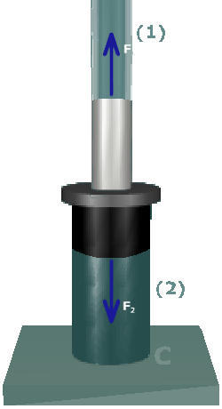
First, consider equilibrium. Draw a free-body diagram around the junction of the two axial members. In this case, draw a free-body diagram around flange .
The cuts through members and , respectively. Assume that there could be an internal axial force in each member cut by the . Further, assume that the force in each member is tension.
Note that we always assume tension even though we intuitively recognize that the internal forces for this particular problem are likely to be compression.