The figure shows the free body diagram around the flange at B. The free body diagram cuts across the rod above and the post below. The axial forces on the rod and the post are F subscript 1 directed vertically upwards and F subscript 2 directed vertically downwards respectively. The parameters corresponding to the rod are A subscript 1, L subscript 1, alpha subscript 1 and E subscript 1. The parameters corresponding to the post are A subscript 2, L subscript 2, alpha subscript 2 and E subscript 2.

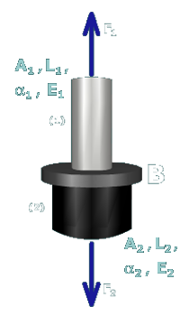
Use the internal force to calculate the normal stresses in members (1) and (2). The normal stress in aluminum rod (1) is

σ1=F1A1=-21,147.216 N200 mm2   =105.7 MPa (C)

and the normal stress in steel post (2) is

σ2=F2A2=-21,147.216 N450 mm2   =47.0 MPa (C)