
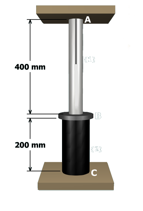
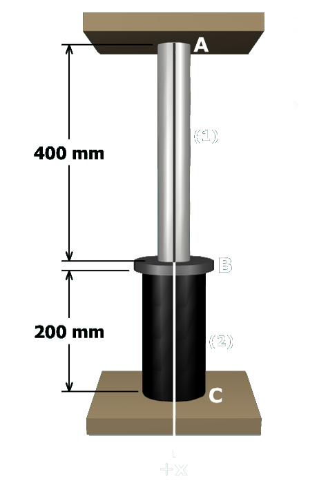
To determine the deflection at point , let's first establish a coordinate system with origin at . The direction for the coordinate system will be directed from to .
The member deformations can be expressed in terms of the deflections at points , , and . For example, the deformation of member can be stated as:
where and are the deflections of points and in the direction.
Points where axial members are connected are called joints. In this structure, , , and are joints. In general, we find deflections at joints and elongations or contractions of axial members.