The elastic torsion formula will be used to compute the shear stress in shaft segments and :
The elastic torsion formula will be used to compute the shear stress in shaft segments and :
For both formulas, the polar moment of inertia will be computed from:
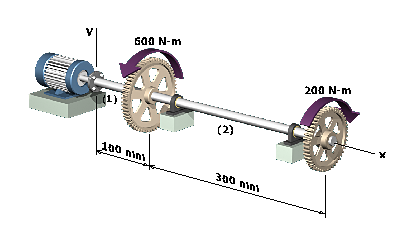
The torque in shafts and will be determined from equilibrium. It will be useful to plot the torques in shafts and in a torque diagram.
After finding and , the angles of twist and in each shaft will be determined.
The rotation angle at will be found by summing and .