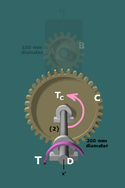
The external torque applied to shaft creates the following torques in the system:
Gear teeth exert a force on gear .
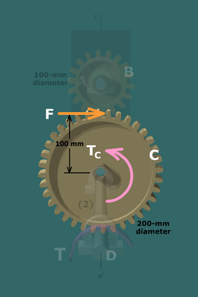
For gear to be in equilibrium, the force exerted by
gear must satisfy:
The external torque applied to shaft creates the following torques in the system: