Diagram shows two vertical shafts A B marked 1 and C D marked 2 centered on the x and x prime axes respectively. A gear of 150 millimeter diameter is at A on shaft 1 at a height of 400 millimeters. A gear of 100 millimeter diameter is at C on shaft 2 at a height of 400 millimeters. Above the gear A a torque T is applied on shaft 1 in the counterclockwise direction. The section on gear A is theta subscript A pointing in the counterclockwise direction. The section on gear C is theta subscript C pointing in the clockwise direction.

If we equate arclengths and account for the opposite rotation directions, we obtain:

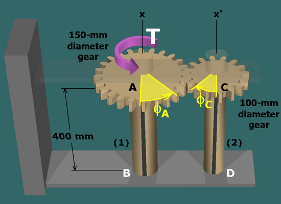
where φA and φC are gear rotation angles.

The twist angle is the difference in rotation angles at the forward and aft ends of a shaft. For shafts (1) and (2):

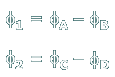
Since B and D are fixed supports, the rotation angles are zero at these points. Therefore: