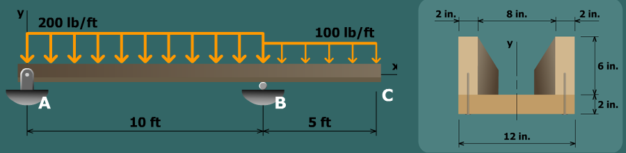
A shear-force and bending-moment diagram will be drawn for the beam to determine the shear force just to the left of support B.
Section properties are needed for the cross section. We will determine the centroid, the moment of inertia about the z centroidal axis, and Q for the 2 in. by 12 in. board.
Since the beam is constructed with individual fasteners (i.e., nails in this instance), we recognize that the problem requires the shear flow formula. Once the shear force and the section properties are known, we will use the shear flow formula to compute the maximum fastener spacing.