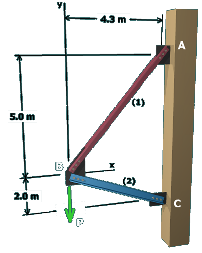
The problem statement gives information on the allowable stress and area of each axial member. From the definition of normal stress, the axial force in each member could be computed from the allowable normal stress according to:

F1=σ1A1                      F2=σ2A2

This approach is not a correct way to solve this type of problem!!

Although allowable stresses are given for the two axial members, it is highly unlikely that both members will be stressed to their respective limits simultaneously by the applied load P.

The figure shows a diagonal member labeled 1 and a horizontal 
member labeled fixed to a column on the right at the points A on top and C below. The diagonal member runs between 
points A and B and the horizontal member runs between the points B and C. Joint B is at a distance of 4.3 meters 
to the left of A and 5 meters below A. Joint C is at a distance of 7 meters directly below A. The load at joint B is 
labeled P and it is directed downwards.