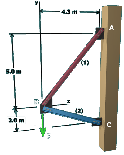
Based on the allowable stress and area given for each axial member, the allowable axial forces can be computed:

F1,allow=σ1 A1          =(180 MPa)(3,080 mm2)          =554,400 N          =554.4 kN


F2,allow=σ2 A2          =(75 MPa)(4,650 mm2)          =348,750 N          =348.75 kN

The figure shows a diagonal member labeled 1 and a horizontal member labeled fixed to a column on the right at the points A on top and C below. The diagonal member runs between 
points A and B and the horizontal member runs between the points B and C. Joint B is at a distance of 4.3 meters to the left 
of A and 5 meters below A. Joint C is at a distance of 7 meters directly below A. The load at joint B is labeled P and it is 
directed downwards.