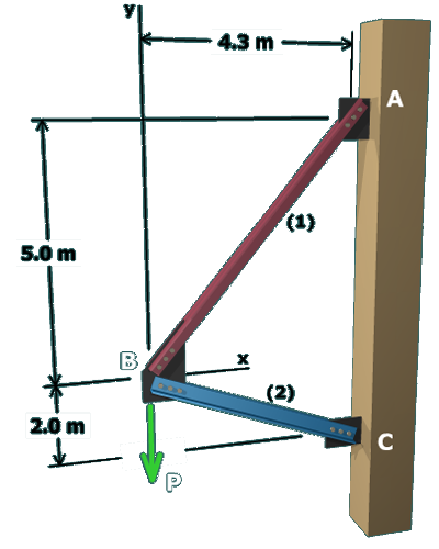
A trial-and-error approach can be used to determine the maximum allowable load P:

6. If F2>Fallow,2, then the original assumption has been proved incorrect. In truth, member (2) controls the load capacity of the structure. Consequently, our earlier calculations must be corrected. This can be done in at least two ways:

a. Set F2=Fallow,2 and solve the equilbrium equations again for F1 and P.

or alternatively,

b. Compute the ratio Fallow,2/F2 and then multiply the values of F1, F2, and P by this ratio.

The figure shows a diagonal member labeled 1 and a horizontal member labeled fixed to a column on the right at the points A on top and C below. The diagonal member runs between 
points A and B and the horizontal member runs between the points B and C. Joint B is at a distance of 4.3 meters to the left 
of A and 5 meters below A. Joint C is at a distance of 7 meters directly below A. The load at joint B is labeled P and it is 
directed downwards.