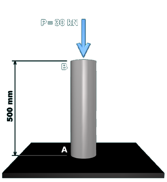
Begin by drawing a free-body diagram at end .
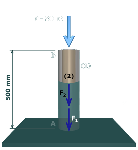
The free-body diagram cuts through tube and core . Internal axial forces and will be assumed to exist in each component. Further, tension forces will be assumed in each, even though intuitively it is expected that the forces will be compression.
We will always assume that internal forces are tension so that we can develop a consistent problem-solving approach for problems of this type.