The figure shows a rigid bar A B C D pinned at A and supported by vertical bars at B and C. The vertical bar at B is labeled 1 and pinned at its top end and the vertical bar at C is labeled 2 and pinned at its bottom end. The separation between A and B is 760 millimeters. The separation between B and C is 760 millimeters and the separation between C and D is 120 millimeters. A load P directed vertically downwards is applied at D.

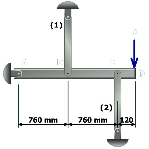
A pin-connected structure is loaded and supported as shown. Member ABCD is a rigid bar that is horizontal before the load P is applied.

Members (1) and (2) are aluminum (E=70 GPa) with cross-sectional areas of A1=A2=160 mm2. Member (1) is 900 mm in length, and member (2) is 1,250 mm. A load of P=35 kN is applied to the structure at D.

a) Determine the axial forces in members (1) and (2).

b) Compute the normal stresses in members (1) and (2).

c) Compute the downward deflection of the rigid bar at D.