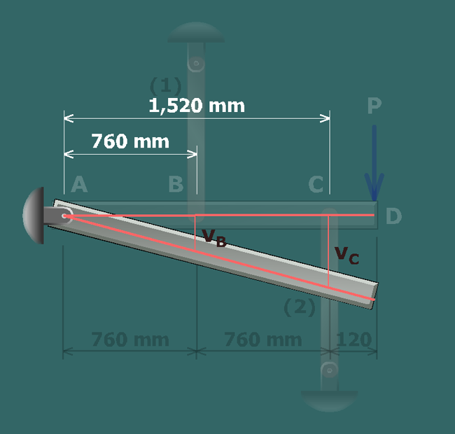
From the rigid bar geometry, the deflections at and are related by:
The axial member deformations are related to the rigid bar deflections by:
These results are combined to obtain the geometry of deformation equation:
From the rigid bar geometry, the deflections at and are related by:
The axial member deformations are related to the rigid bar deflections by:
These results are combined to obtain the geometry of deformation equation: