The figure shows a rigid bar A B C D pinned at A and supported by vertical bars at B and C. The vertical bar at B is labeled 1 and pinned at its top end and the vertical bar at C is labeled 2 and pinned at its bottom end. The separation between A and B is 760 millimeters. The separation between B and C is 760 millimeters and the separation between C and D is 120 millimeters. A load P directed vertically downwards is applied at D.

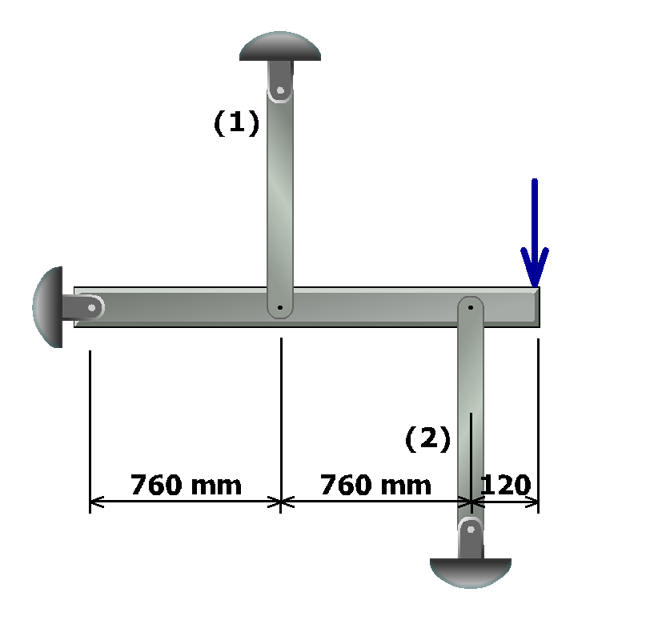
To determine the geometry of deformation relationship, first sketch the rotated position of rigid bar ABCD after load P has been applied.