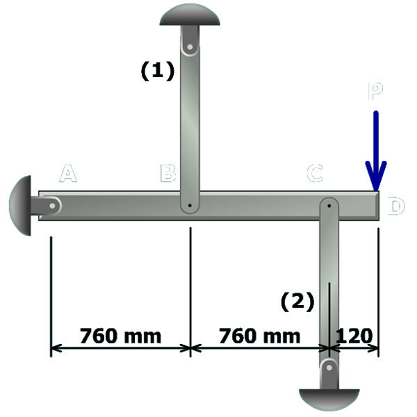
The equilibrium equation
and the compatibility equation:
can be solved simultaneously to determine and .
To compute the normal stress in each member, divide the internal axial force by the cross-sectional area :

The equilibrium equation
and the compatibility equation:
can be solved simultaneously to determine and .
To compute the normal stress in each member, divide the internal axial force by the cross-sectional area :