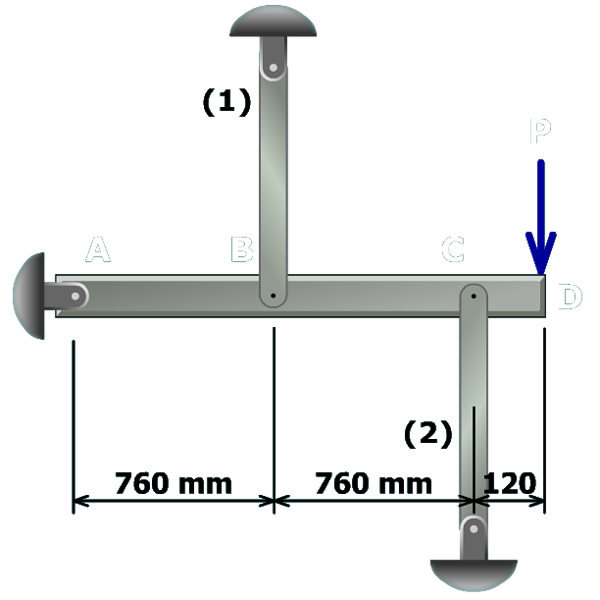
The figure shows a rigid bar A B C D pinned at A and supported by vertical bars at B and C. The vertical bar at B is labeled 1 and pinned at its top end and the vertical bar at C is labeled 2 and pinned at its bottom end. The separation between A and B is 760 millimeters. The separation between B and C is 760 millimeters and the separation between C and D is 120 millimeters. A load P directed vertically downwards is applied at D. To solve this problem, a five-step procedure will be used.

Step 5 – Solve simultaneously

Solve the equilibrium and compatibility equations simultaneously for the axial forces in members (1) and (2). Once these forces are known, the normal stresses and the rigid bar deflections at D can be determined.