Home
Chapter 6: Torsion
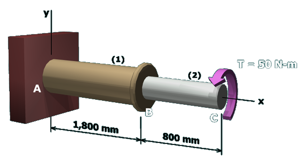
M6.6: Twisting of a Compound Torsion Member
Angle of Twist in Segment (1)
State the Problem
Plan the Solution
Table of Contents
Angle of Twist in Segment (1)
Allowable Angle of Twist in Segment (2)
Minimum Polar Moment of Inertia for Segment (2)
Minimum Diameter for Segment (2)
scene
4
of
7
Cut a free-body diagram
(
FBD
)
through segment
(
1
)
.