• Equilibrium
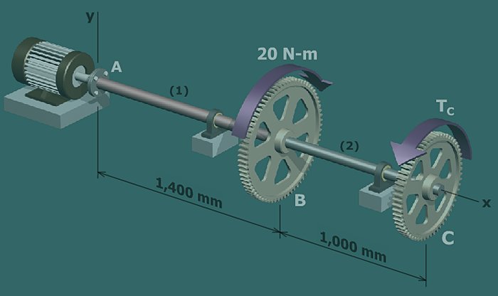
Cut free-body diagrams through shafts and to derive
equations for internal torques and in terms of the unknown
torque .
• Torque-twist relationships
Express the relationship between internal torque and angle of twist for each shaft.
• Geometry of deformation
The angle of rotation at will be the sum of the twist angles in shafts
and .
• Equation for rotation angle at
Substitute the torque-twist relationships into the geometry of deformation equation to derive an expression for the rotation angle at .
• Express in terms of
Substitute the expressions for and derived from equilibrium into the equation for the rotation angle at .
• Solve for
Manipulate this equation and solve for .