Diagram shows a shaft A B with an aluminum segment on the outside and a brass shaft in the inside. Both the shafts are centered on the central axis x. A torque T is applied at B. The radial and longitudinal lines are shown on the shaft. The deformation of the shaft is shown with a counterclockwise segment of angle phi subscript B, angle of twist.

In summary, the internal torques in shafts (1) and (2) are:

T1=675.7 N-mT2=724.3 N-m

Shear stresses are:

τ1=54.83 MPaτ2=67.31 MPa

The rotation of end B is:

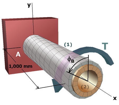
ϕB=+0.08435 rad   =+4.83 deg

Finished